Liquid Propulsion ECU
ENO is a regeneratively cooled custom liquid rocket engine developed by Duke AERO designed to produce 2500 newtons of thrust using nitrous oxide and kerosene. The propulsion test platform is a critical component of the ENO development program, providing a controlled environment for validating engine performance and characterizing combustion behavior.
Electrical Overview
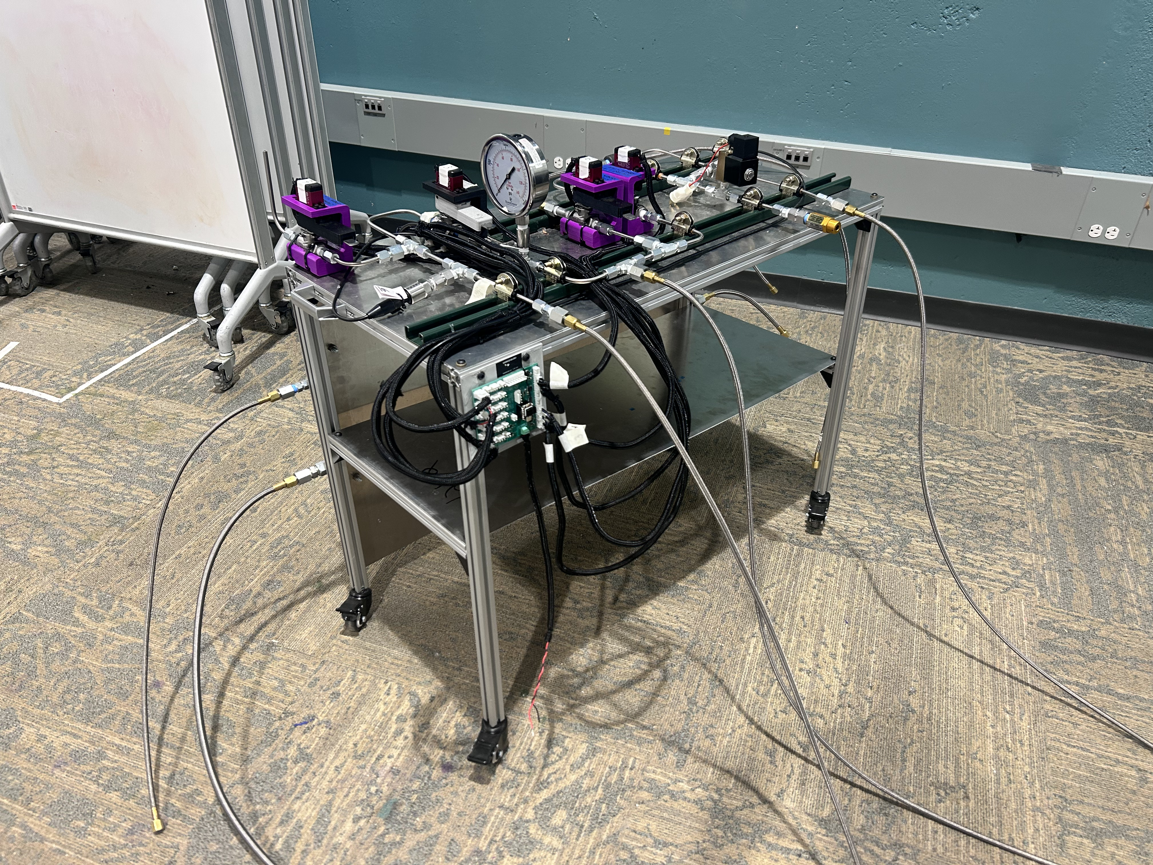
The ENO test platform is built around a network of pressurized tanks, tubing, valves, and sensors. The previous system consisted of a mess of cables, various protoboards, an Arduino UNO, and an external DAQ. The result was a system completely inadequate for the reliability and consistency required by a liquid rocket engine. Each test required hours of wiring and troubleshooting. To improve both reliability and simplicity, I designed a fully integrated engine control unit PCB capable of handling all the previous functionalities on a single dedicated board. Currently, I'm leading a team in developing a 2nd iteration of the board with additional features and modifications to issues found during testing of V1.0.
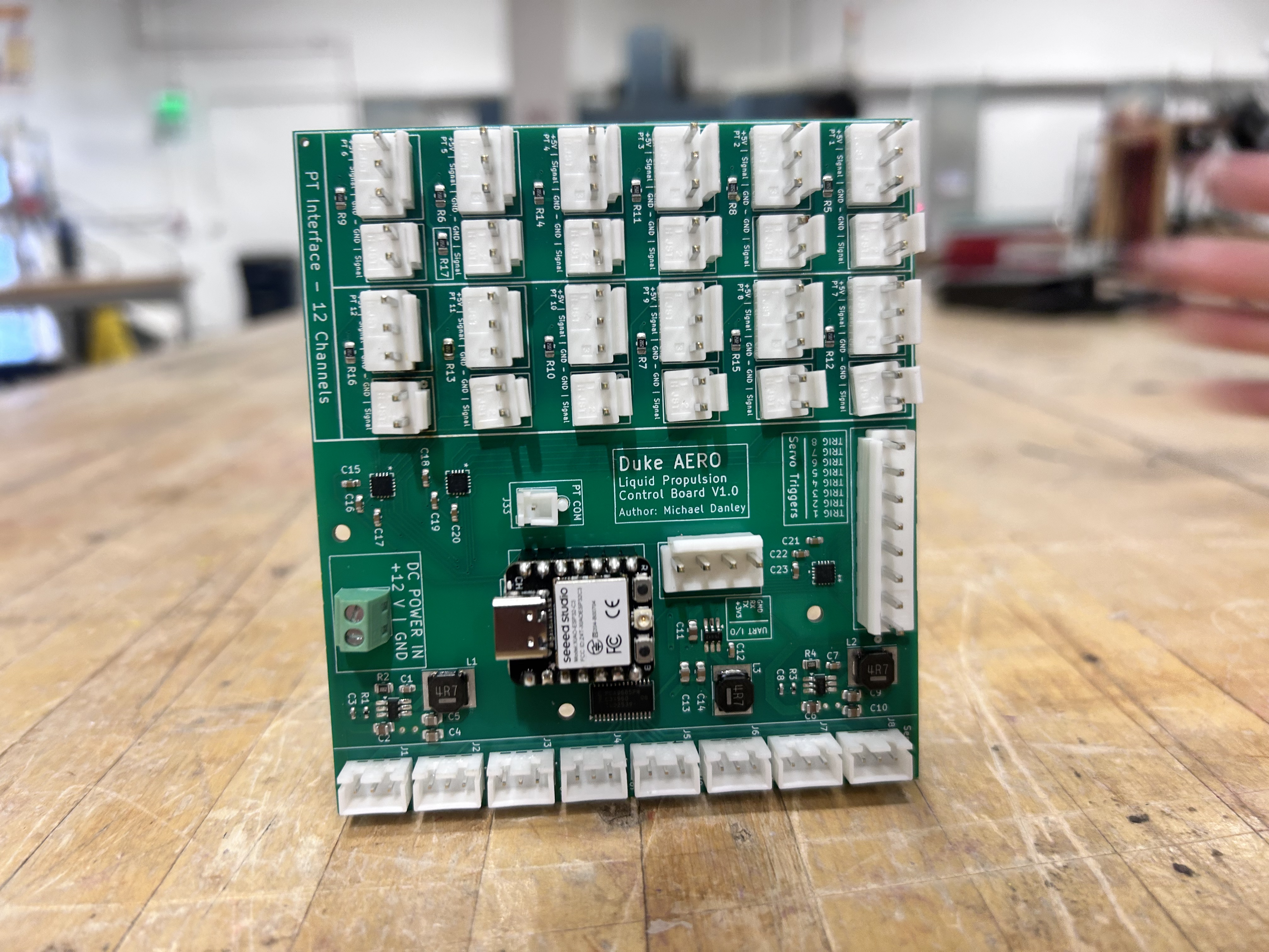
ENO ECU V1.0
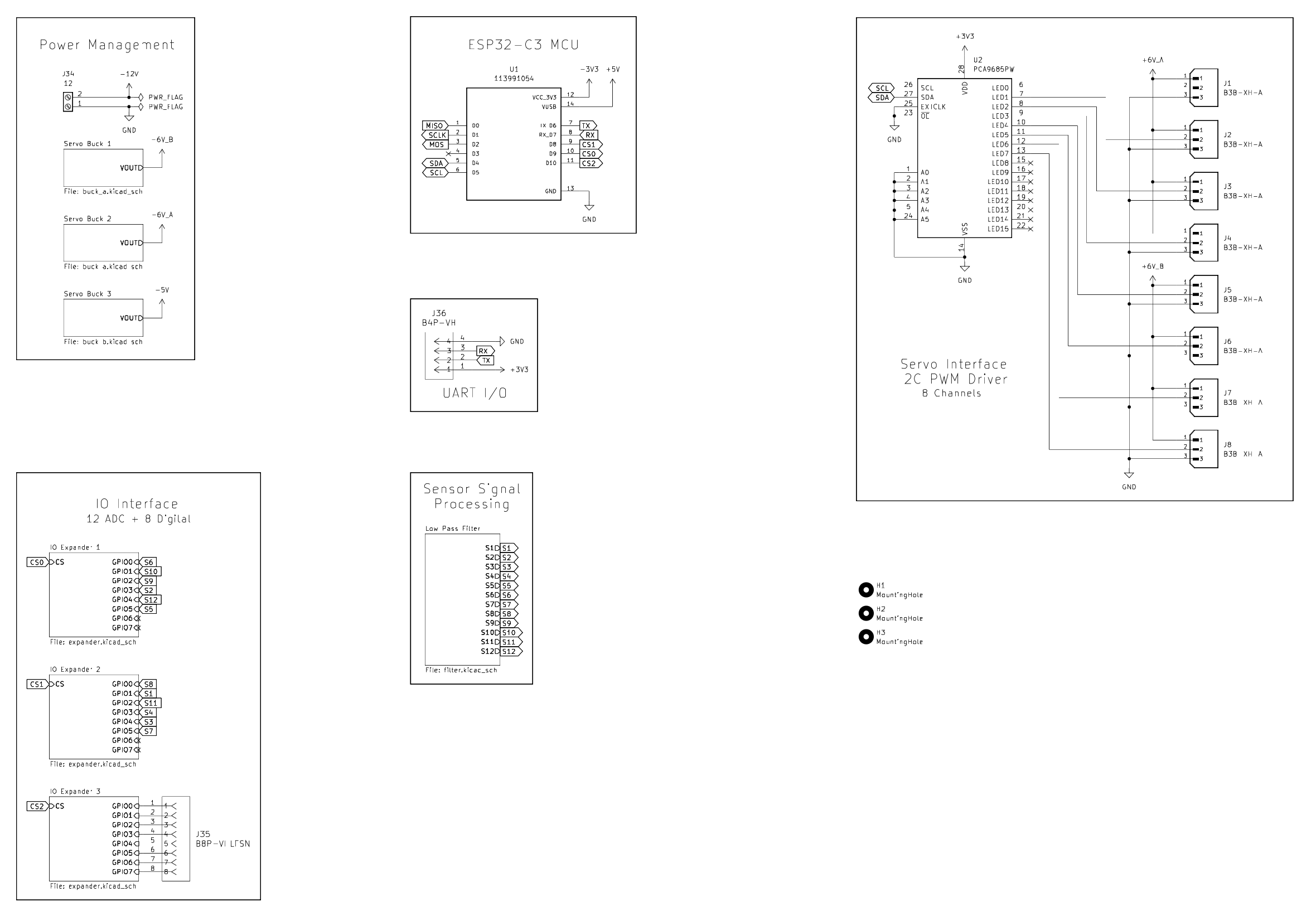
The ENO ECU V1.0 focuses on high-frequency data acquisition, power management, and servo control. Powered by an ESP32-C3 MCU, the board can use WiFi to communicate with a connected laptop to both send telemetry and recieve wireless servo commands. This iteration also contains additional connectors to interface with an external DAQ.
V1.0 Design Goals
| Objective | Component | Description |
|---|---|---|
| PT Sampling | TLA2518 ADC | The TLA2518 is an 8-channel, 12-bit Analog-to-Digital Converter. It uses an SPI interface to provide high-speed monitoring of pressure transducer (PT) signals with integrated hardware averaging to reduce noise. |
| Servo Control | PCA9685 PWM Driver | The PCA9685 is an I2C-controlled 16-channel LED/PWM controller. It offloads timing-critical pulse-width modulation from the main MCU, providing 12-bit resolution for precise angular control of servos. |
| Servo Power | AP63300 Buck Converter | The AP63300 is a 3A synchronous buck converter capable of converting 12V DC battery voltage to a stable 6V rail for servo power. |
| Logic Power | AP63205 Buck Converter | The AP63205 is a 2A low-noise fixed 5V buck converter capable of converting 12V DC battery voltage to a stable 5V rail for the MCU board which provides 3V3 for digital logic. |
| IO Hardware | JST Connectors | XH-JST and VH-JST Connectors are used for secure, wire-to-board connections. Their keyed housings prevent reverse-polarity errors during maintenance. |
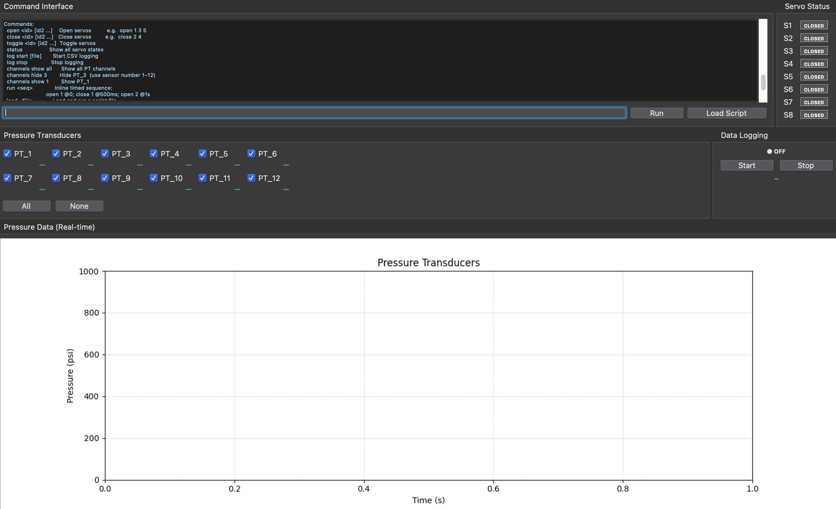
V1.0 User Interface
The user interface is a Python program that wirelessly pairs with the ECU and is capable of streaming live telemetry data and sending servo commands. A custom CLI allows the user to interact with the system while a real-time graphical display plots calibrated pressure data from up to twelve transducers using a configurable moving average filter. The application supports timed command sequences and script execution for automated valve actuation, along with live channel selection and servo state indicators. Telemetry and actuator states can be logged to CSV for post-test analysis, making the tool suitable for both live monitoring and structured experimental runs.
V1.0 Schematic
 Download Full Schematic
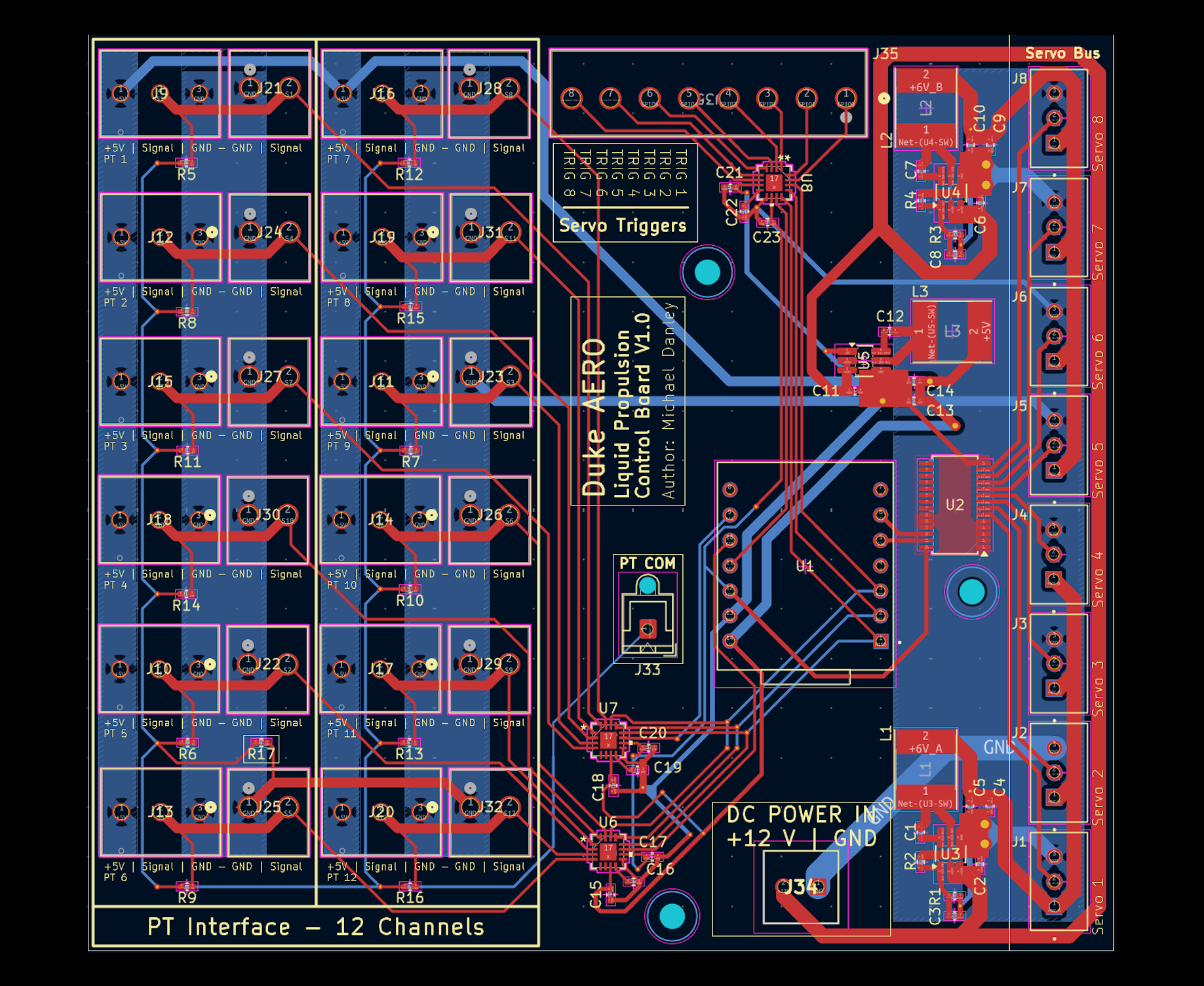
V1.0 PCB Layout
V1.0 Testing
Cold flow testing allows us to test ENO flow performance and measure pressure changes through components in our test platform. V1.0 reduced electrical setup time from hours to minutes while simplifying the interface and removing the need for a bulky external DAQ. The integrated sampling solution more than doubled the polling frequency from 40 hz to 100 hz. However, testing also revealed undersized current capacity for servos and noisy sampling due to routing. V2.0 attempts to address those issues.
ENO ECU V2.0
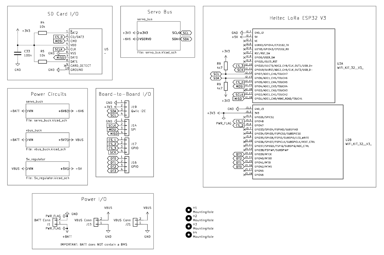
The ENO ECU V2.0 transitions to a modular, two-board architecture to isolate EMI from analog sampling. Key upgrades include enhanced power circuitry with low-noise regulators, integrated support for thermistors and load cells, and an ESP32-S3 core featuring LoRa connectivity and local data logging for superior reliability.
V2.0 Design Goals
| Objective | Component | Description |
|---|---|---|
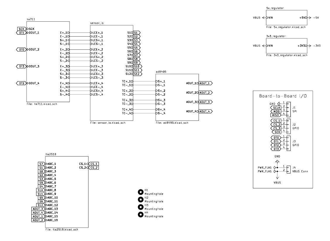
| PT Sampling | TLA2518 ADC | The TLA2518 is an 8-channel, 12-bit Analog-to-Digital Converter. It uses an SPI interface to provide high-speed monitoring of pressure transducer (PT) signals with integrated hardware averaging to reduce noise. |
| Thermistor Sampling | AD8495 Amplifier | The AD8495 is an op-amp that amplifies analog signals from K-type thermocouples before sending the signals to the TLA2518 ADC |
| Load Cell Sampling | HX711 ADC | The HX711 is an op-amp ADC that is able to read analog signals from load cells on the testing platform and send 24-bit readings to the MCU. |
| Servo Control | PCA9685 PWM Driver | The PCA9685 is an I2C-controlled 16-channel LED/PWM controller. It offloads timing-critical pulse-width modulation from the main MCU, providing 12-bit resolution for precise angular control of servos. |
| Servo Power | TPS56A37 Buck Converter | The TPS56A37 is a 10A buck converter paired with increased bulk capacitance to handle large current spikes from servo power draw. |
| VBUS Power | TPS5430 Buck Converter | The TPS5430 is a 3A high-efficiency buck converter that converts 12V DC battery voltage to a stable VBUS voltage that is linearly regulated for logic applications. |
| Logic Power | TPS7A4701 LDO | The TPS7A4701 is a low-noise, high-PSRR linear regulator that provides a clean 3.3V supply from the VBUS supply for sensitive analog components, minimizing EMI and ensuring stable operation. |
| IO Hardware | JST Connectors | XH-JST and VH-JST Connectors are used for secure, wire-to-board connections. PH-JST and SH-JST Connectors are used for secure, board-to-board connections |
V2.0 Schematics
Control Board Schematic
 Download Full Schematic
Sampling Board Schematic
 Download Full Schematic
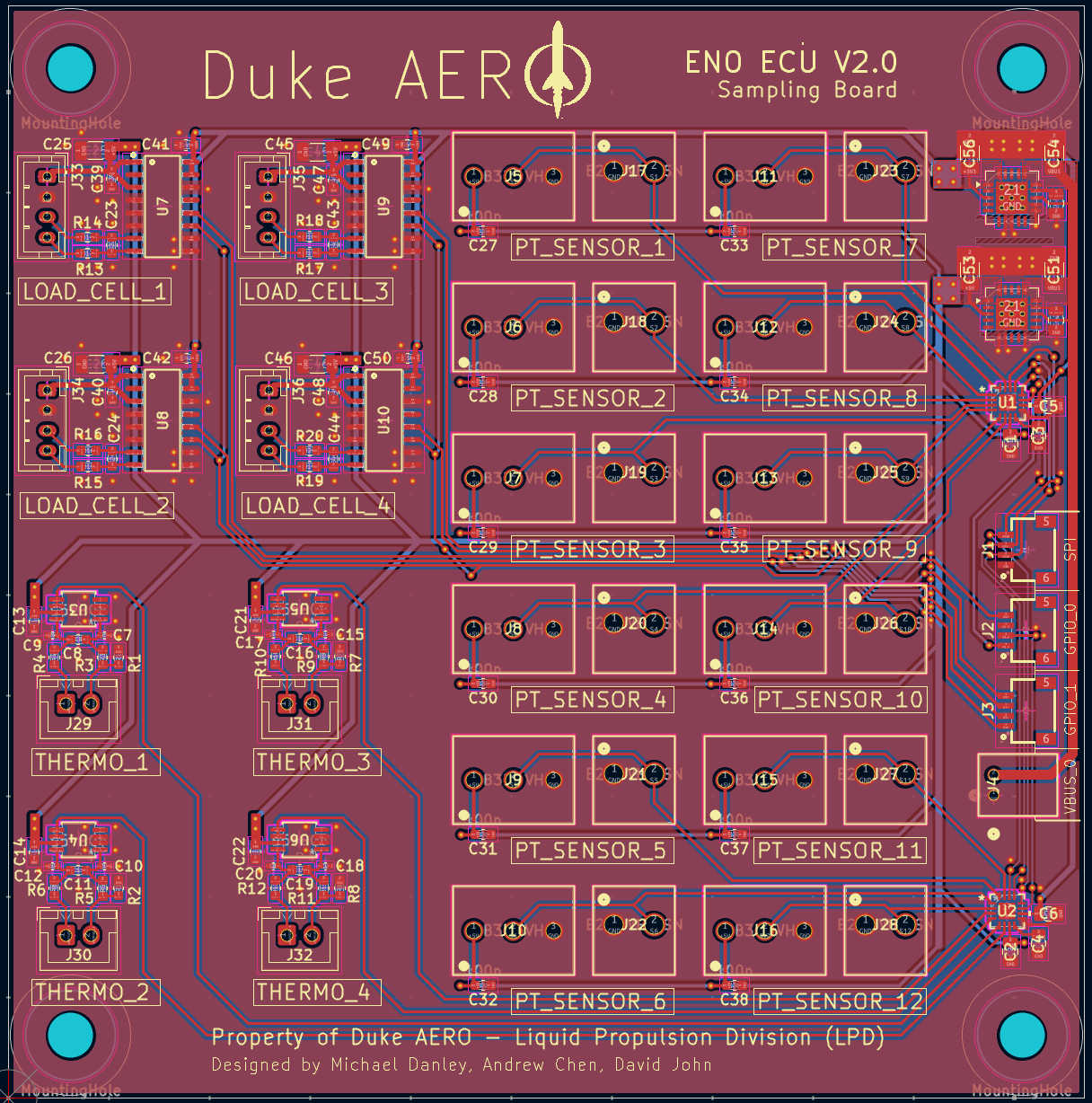
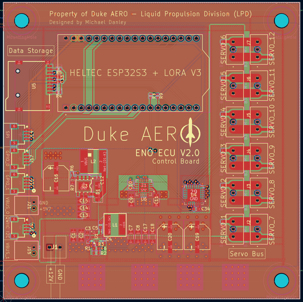
V2.0 PCB Layout
Control Board Layout
Sampling Board Layout