Project ORCA
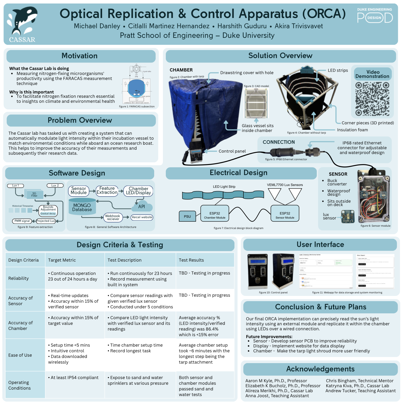
ORCA (Optical Replication & Control Apparatus) is a high-fidelity environmental emulation system designed to replicate real-time solar intensity within marine incubation vessels. As the Electrical Systems Engineer, I lead the end-to-end hardware lifecycle, including the design, fabrication, and validation of all control electronics. After a successful proof-of-concept phase in Fall 2025, the project is currently in active fabrication for a ruggedized, research-grade unit ready for offshore deployment.
Accurately measuring nitrogen-fixing microorganism activity is essential for advancing our understanding of marine ecosystems and the impacts of climate change. FARACAS is a novel measurement technique; however, its accuracy hinges heavily on precise replication of natural light intensity. The Cassar lab at Duke University tasked our team with creating a system that can automatically modulate light intensity within their incubation vessel to match environmental conditions while aboard an ocean research boat. To best meet the needs of our client, our team identified a set of design goals that our solution should aim to achieve.
| Design Criteria | Target Metric |
|---|---|
| Reliability | ➤ Continuous operation for at least 23 out of 24 hours a day ➤ Minimal maintenance for at least 2 years |
| Accuracy of Sensor | ➤ Must update in real-time on an evenly set interval ➤ Measurement accuracy within 15% of a verified lux sensor |
| Ease of Use | ➤ Setup time under 5 minutes ➤ Intuitive manual and automatic light intensity control ➤ Data can be downloaded wirelessly in under 2 minutes |
| Operating Conditions | ➤ At least IP54 compliant ➤ Measurement unit must work in temperatures above 60° C |
Initial Prototyping (Fall 2025)
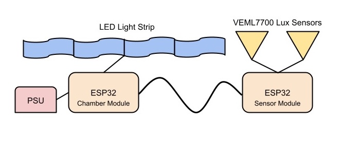
The system features a split architecture consisting of an outdoor sensor module and an internal chamber module, linked via an RJ45 interface for robust power and data transmission. The sensor module relies on an ESP32-C3 microcontroller—powered by an external buck converter that steps down 24V to 3.3V—to collect real-time solar intensity data from dual VEML7700 lux sensors via I2C. This data is routed via UART through a MAX3485 RS-485 transceiver over the connecting cable to the chamber module.
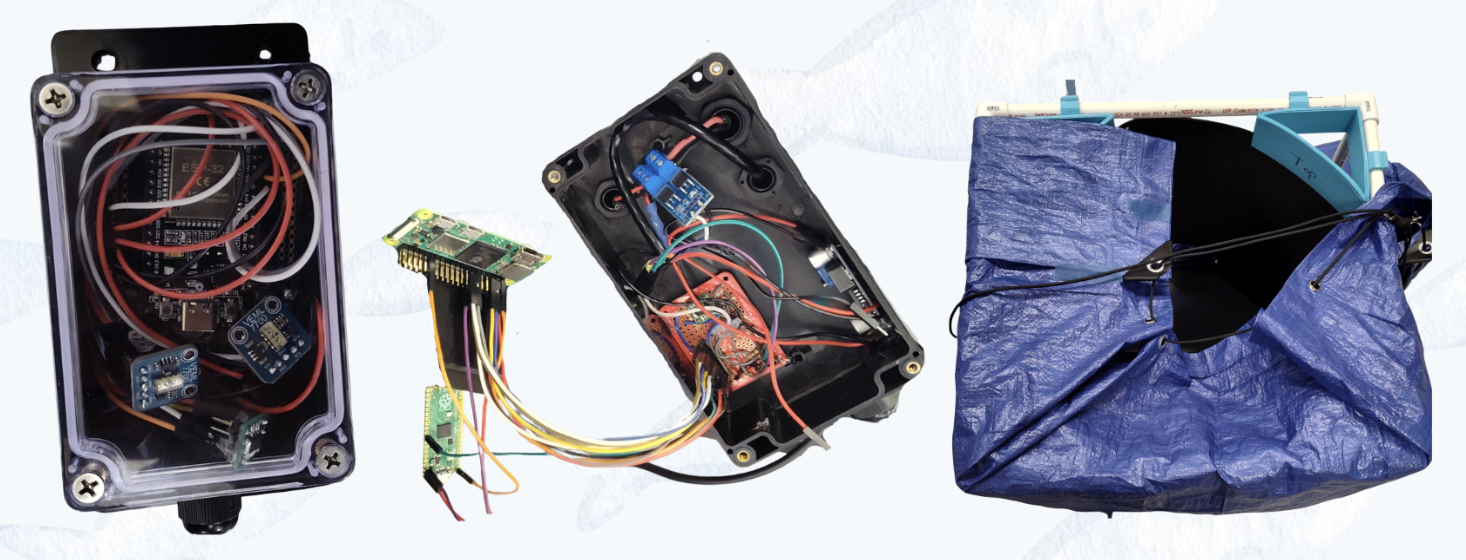
Within the chamber unit, a receiving MAX3485 transceiver routes the incoming data to a central ESP32 microcontroller, which also interfaces with the manual front-panel IO. The ESP32 processes the UART data stream to calculate a precise PWM duty cycle for a MOSFET driver board; this board modulates the high-amperage 24V LEDs surrounding the incubation vessel to accurately replicate the detected outdoor light intensity, while the ESP32 simultaneously manages the system's wireless interfacing and local data logging capabilities. More information on the initial prototype can be found in the following design poster our team presented at the Duke University EGR 101 Design Expo on December 8th, 2025.
RJ45 Interface Design
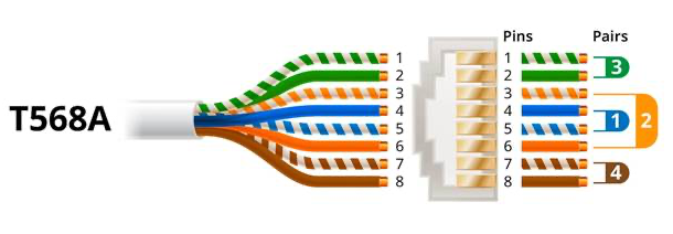
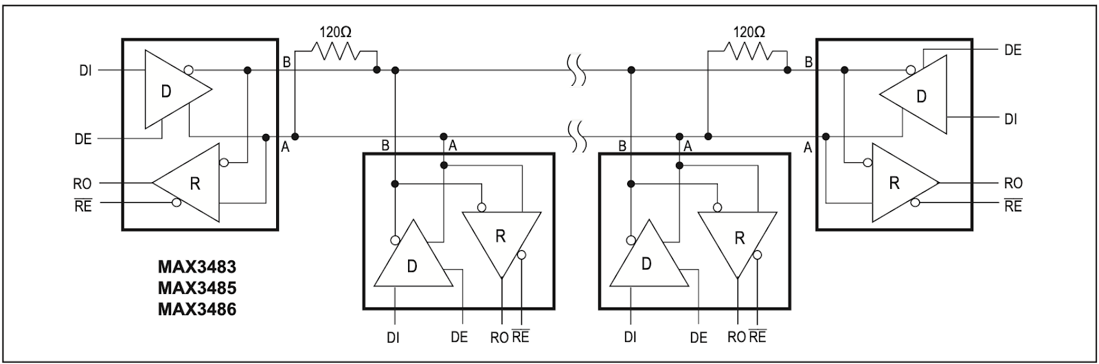
RS-485 is a differential serial communication protocol designed for reliable long-distance wired connections. I selected this protocol for its strong EMI immunity, achieved through its twisted-pair differential signaling implementation, which enables communication over distances exceeding 1,000 meters. For the physical interface, I selected an RJ45 connector, which provides four twisted pairs (eight total conductors). RX data, 24 V power, and ground are each assigned a dedicated twisted pair to minimize interference and signal degradation. Power is transmitted at the supply voltage and buck-converted at the sensor module to mitigate voltage drop from cable resistance and reduce current draw through the cable.
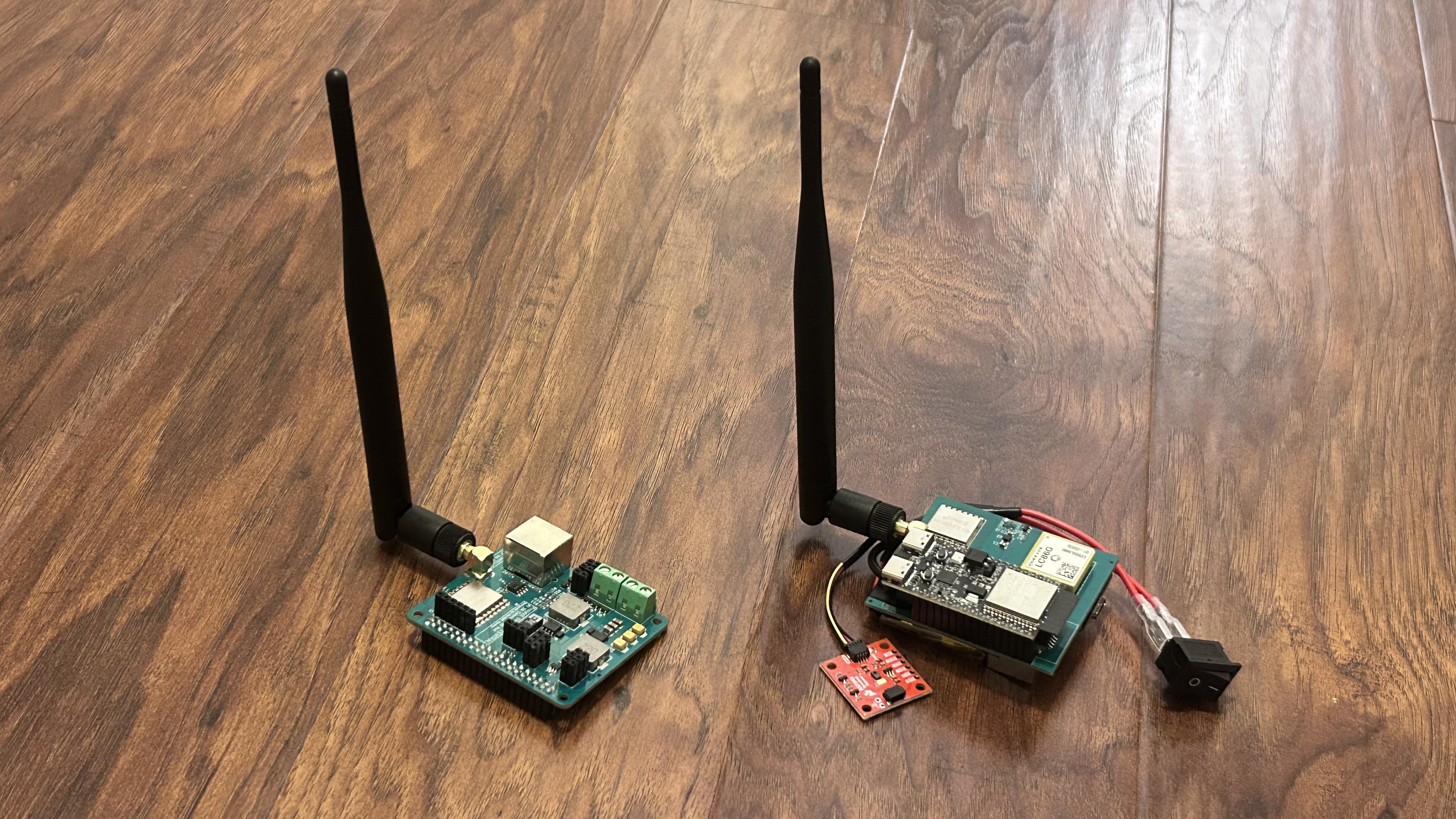
Research-Grade Hardware (Spring 2026)
With prototype testing data and feedback from our client, we're currently developing research-grade hardware that aims to enchance reliability, improve on previous design flaws, and add expanded functionality. Both the chamber and module electrical designs have moved onto PCBs with integrated power management, LoRa communication, and LED control circuitry.
Chamber Module PCB
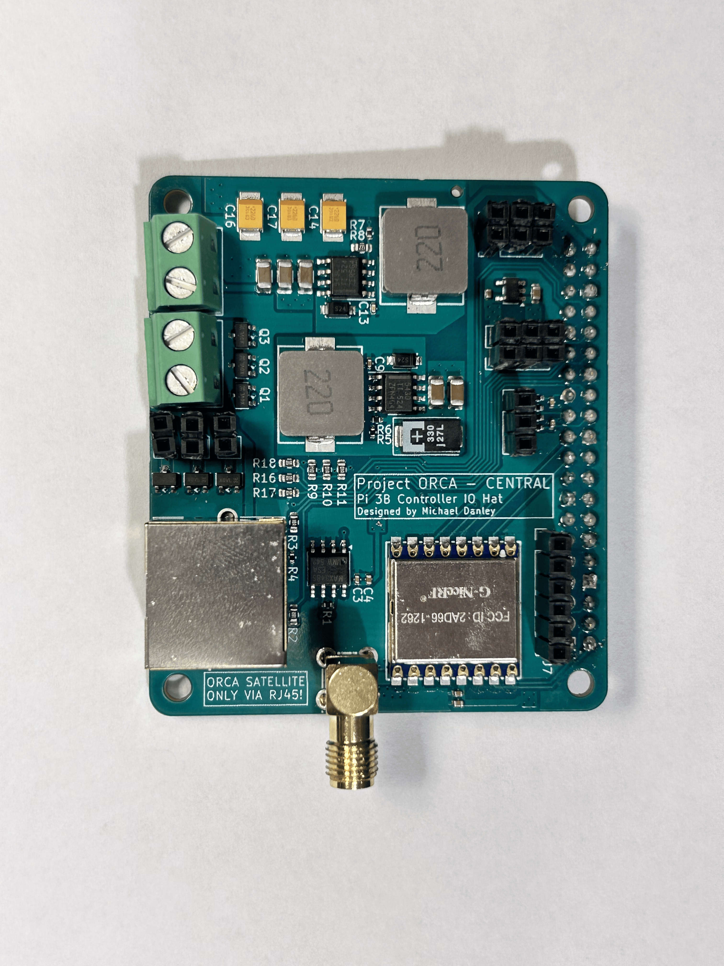
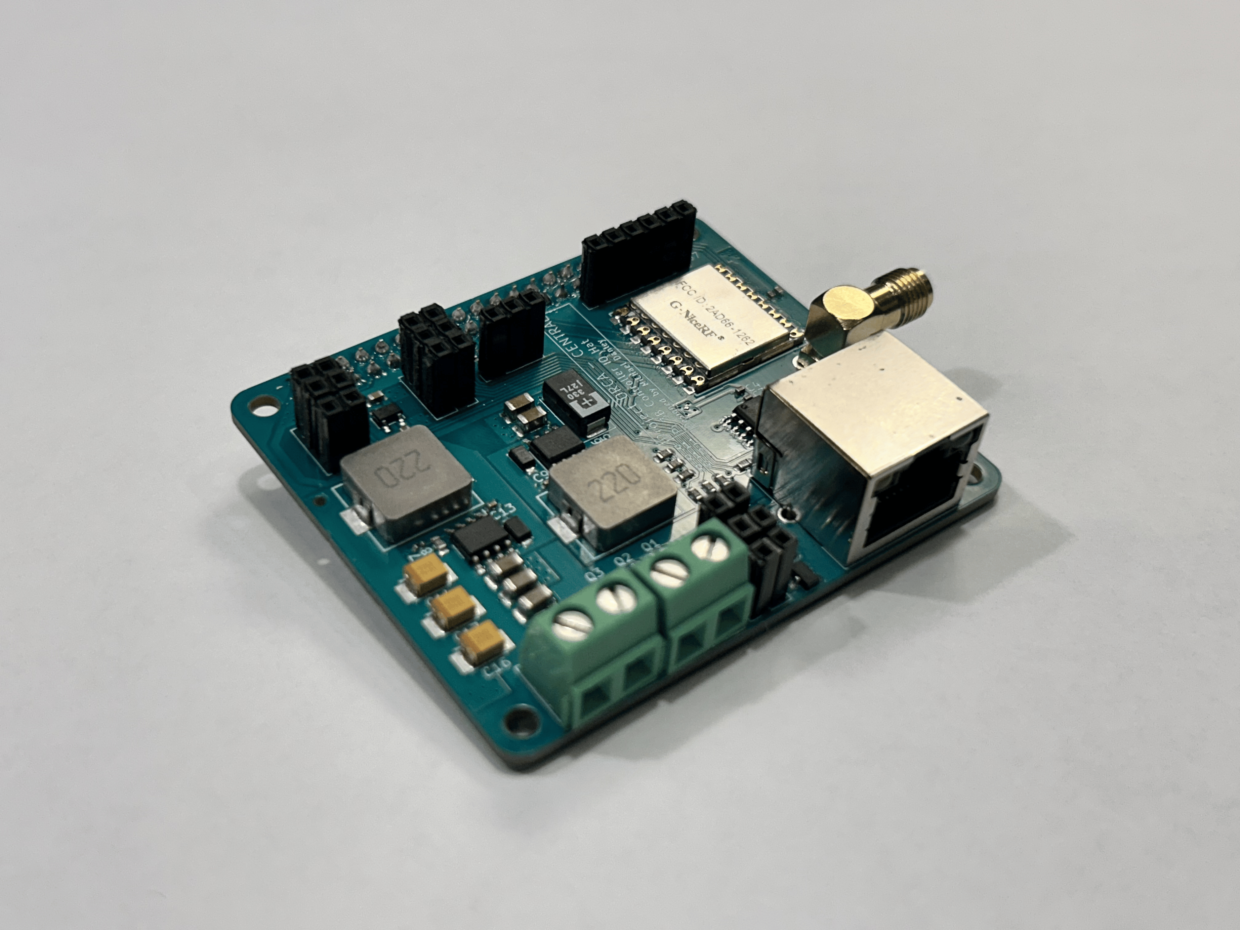
The chamber module PCB is designed in the Pi HAT formfactor for direct integration with a Raspberry Pi 3B. It integrates power circuitry, communication systems, chamber control circuitry, and front IO interfacing onto one compact board. A single 24V power connection onto the board powers all chamber systems including the Pi itself, chamber LEDs, and the sensor module if connected via RJ45.
| Objective | Component | Description |
|---|---|---|
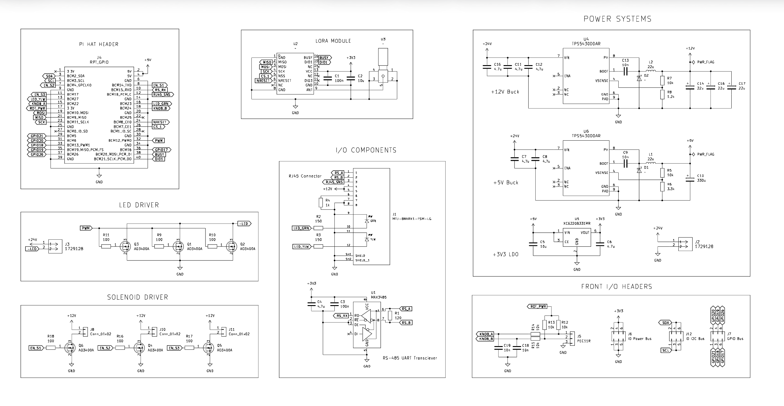
| Power Circuitry | TPS5430 | TPS5430 buck converters provide a 12V and 5V rail from the 24V input to power chamber hardware, the Raspberry Pi 3B, and the RJ45 power interface. |
| Communication Systems | MAX3485, LORA1262 | The PCB implements the same MAX3485 interface from prototyping with the addition of a LORA1262 chip capable of recieving long-range wireless communication from the sensor module anywhere on the ship. |
| Chamber Control | AO3400 | These MOSFETs are used to control both the chamber LEDs via PWM and solenoid valves controlling fluid flow into and out of the chamber, an additional feature requested by our client. |
| Front IO | Pin Headers | To maximize compatibility, all IO connectors are standard 2.54mm pin headers. A rotary encoder circuit is also embedded into the board for native rotary dial support. |
Chamber Module Schematic
 Download Full Schematic
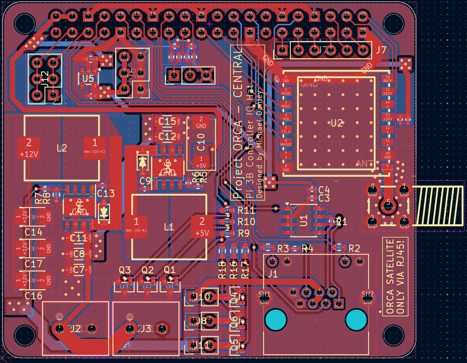
Chamber Module PCB Layout
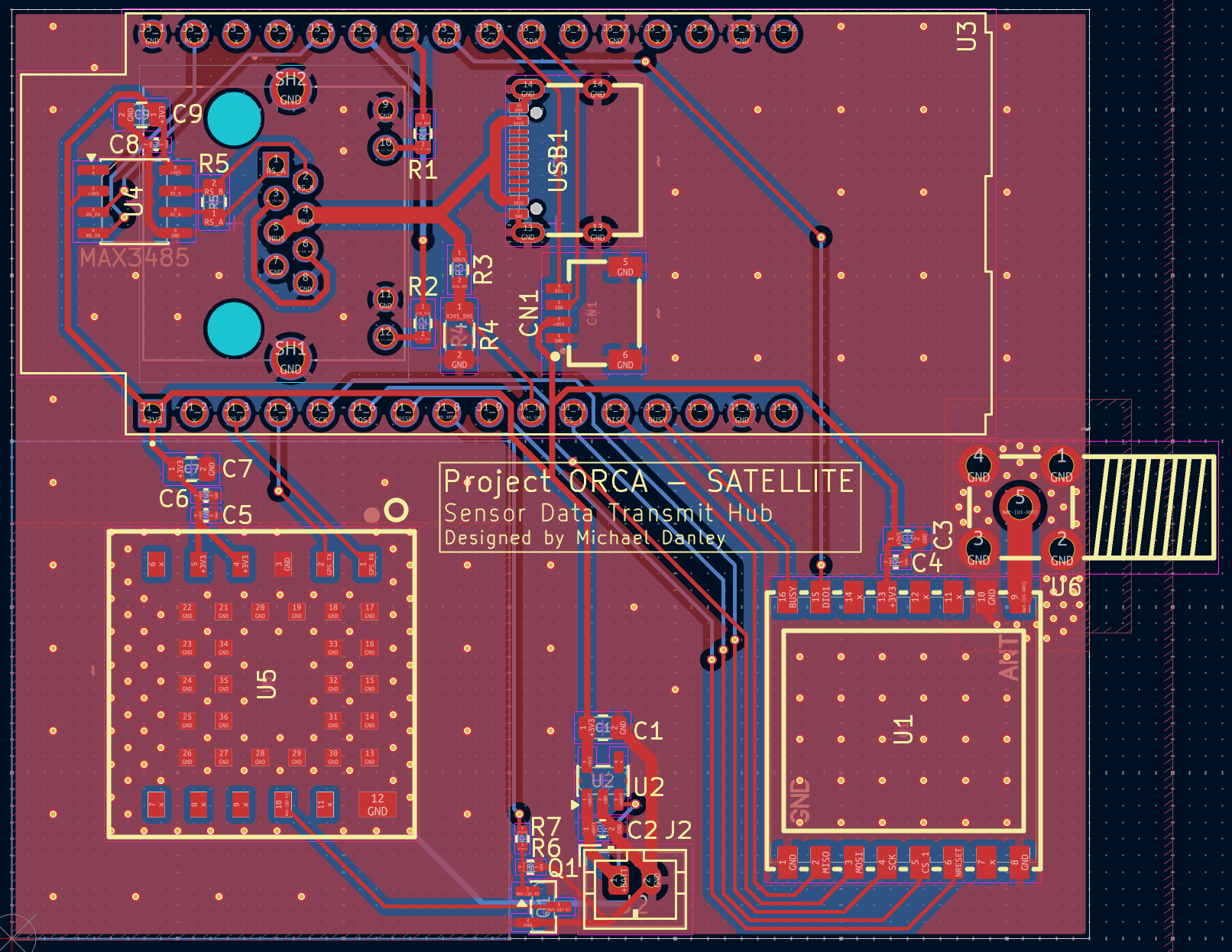
Sensor Module PCB
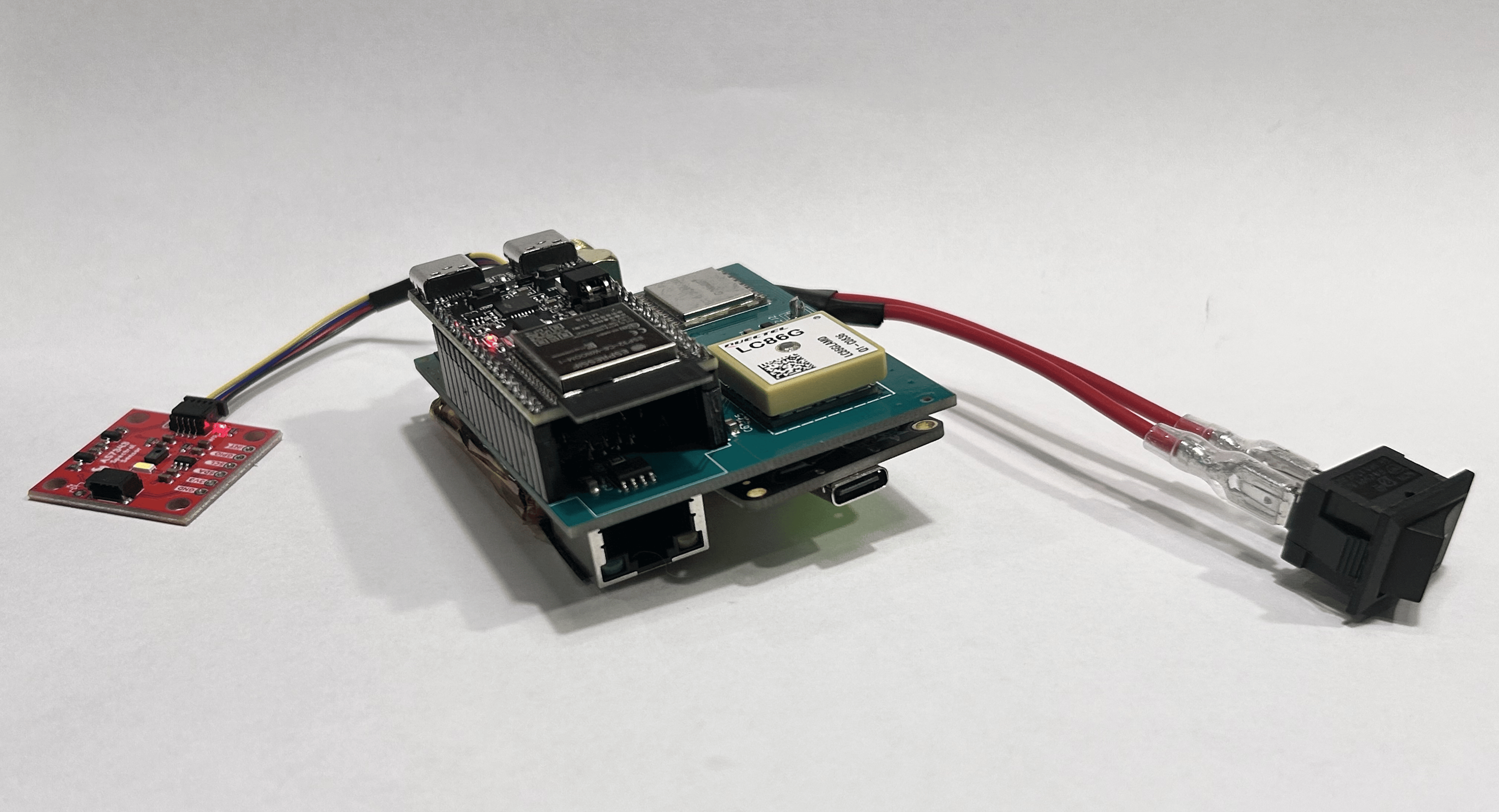
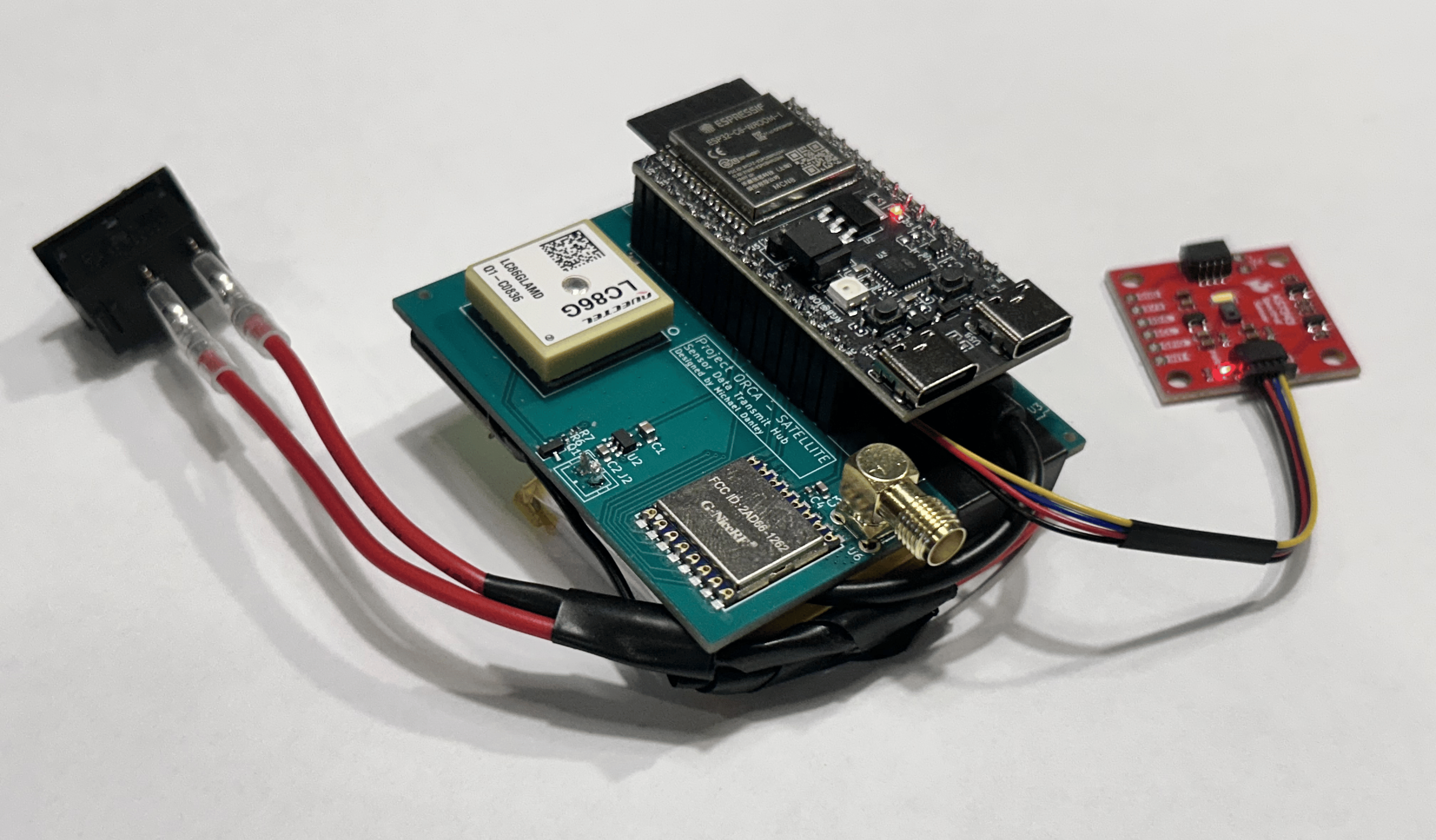
The chamber module PCB is designed around the ESP32-C6 DevKitC-1 due to its extensive GPIO and low-power core enabling efficient battery operation. An AS7343 breakout replaces the original VEML7700 due to its multi-spectral sensing capabilities. A BQ25185 battery controller breakout handles battery management, allowing the sensor module to work completely independent of any wired connection. The board also includes LoRa for wireless communication and GPS for position and time data.
| Objective | Component | Description |
|---|---|---|
| Battery Management | BQ25185 Breakout | The BQ25185 breakout manages a 3000 mAh LiPo cell with near-MPPT capability for solar charging from an ETFE coated panel placed outside the sensor module enclosure. Additionally, the breakout can draw power from the RJ45 connector located on the PCB. |
| Power Circuitry | XC6220 | The BQ25185 provides unregulated ~4.5V to the sensor module PCB. The XC6220 is a high-efficiency LDO regulator used to provide stable, low-noise 3.3V power to the board. |
| Communication Systems | MAX3485, LORA1262 | The PCB implements the same MAX3485 interface from prototyping with the addition of a LORA1262 chip capable of sending long-range wireless communication to the chamber module anywhere on the ship. |
| Light Sensing | AS7343 Breakout | The AS7343 breakout can sample 14 different wavelengths across and beyond the visible spectrum allowing it to capture a spectrum of intensities for a more accurate representation of light conditions. |
| GPS | LC86GLA | The LC86GLA was selected for its integrated patch antenna and ultra low power consumption. GPS data provides both time and location allowing us to calculate solar inclination that may impact the accuracy of our spectral sampling. |
Sensor Module Schematic
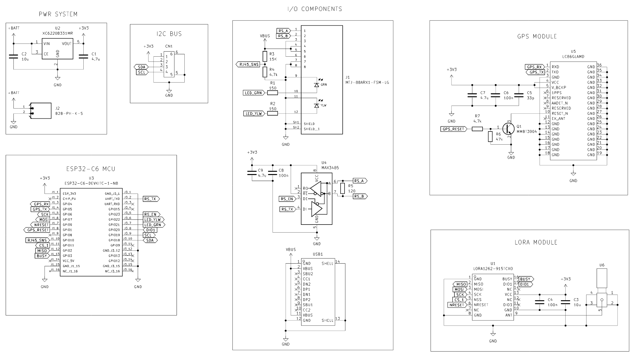 Download Full Schematic
Sensor Module PCB Layout